
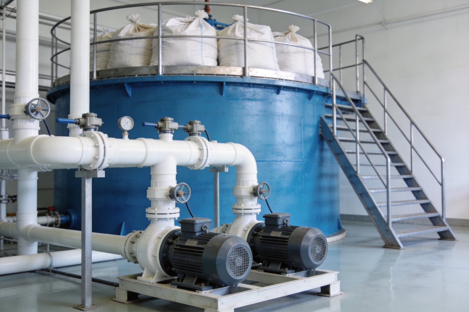
Ask a plant manager why a membrane-cell electrolyzer lost current efficiency two years early and the answer is rarely the membrane itself — it is almost always the brine. A properly engineered brine saturation system is the quiet foundation of every high-concentration (10–15%) sodium hypochlorite generator: it converts raw salt and softened water into a steady stream of saturated, clean brine that the ion-exchange membrane cell can run on for years. Underdesign it, and the symptoms arrive in sequence — falling current efficiency, rising cell voltage, frequent acid washing, premature membrane and electrode replacement. This guide covers the engineering decisions behind a brine saturation system that performs: salt consumption calculations, saturator hydraulics, water softening, concentration control, materials of construction, and the design mistakes we see most often in the field.
Table of Contents
- Why the Brine Saturation System Sets the Ceiling on Electrolyzer Performance
- Salt Consumption and Brine Demand: Sizing Fundamentals
- Saturated Brine Chemistry and the Operating Window
- Salt Saturator Design: Dissolver Hydraulics That Actually Work
- Water Softening and Brine Clarification Ahead of the Membrane Cell
- Instrumentation and Automatic Concentration Control
- Materials of Construction for Saturated Brine Service
- Common Brine Saturation System Design Mistakes
- Frequently Asked Questions
Why the Brine Saturation System Sets the Ceiling on Electrolyzer Performance
An ion-exchange membrane cell is a precision device operating at 4–6 kA/m² of current density. The membrane passes sodium ions and rejects everything else — and it pays for every impurity and every concentration excursion it sees. Calcium and magnesium in the brine precipitate as hydroxides inside the membrane structure, raising cell voltage and cutting current efficiency; the full failure chain is documented in our analysis of ion exchange membrane degradation and life-extension strategies. Under-saturated brine is equally damaging: a cell fed below its design NaCl concentration suffers sodium-ion starvation at the anode, which drives oxygen evolution and accelerates coating wear on the electrodes.
The economics compound quickly. A generator running on poor brine typically needs dilute acid washing (1–3% HCl, 30 minutes to 2 hours) every few weeks instead of every few months — and every unnecessary acid wash shortens membrane life. Meanwhile, unstable brine concentration makes product concentration unstable, breaking the accuracy of the entire downstream dosing chain.
Salt Consumption and Brine Demand: Sizing Fundamentals
Sizing starts from electrochemistry. The overall reaction in a membrane-cell high-concentration sodium hypochlorite generator is NaCl + H₂O → NaClO + H₂↑. Theoretical consumption is therefore 0.785 kg of NaCl per kilogram of NaClO produced. On the available-chlorine basis used by product standards (1 kg NaClO ≈ 0.95 kg available Cl₂), that is 0.82 kg of salt per kilogram of available chlorine. Apply a design factor of 1.05–1.10 to cover purification purge, spills and start-up losses, and the working figure becomes roughly 0.86–0.91 kg/kg Cl₂.
For reference, Faraday’s law gives the electrical side of the same balance: 1 A·h of charge theoretically yields 1.323 g of Cl₂ and 1.389 g of NaClO, so a 10 kA cell current produces about 13.9 kg/h of NaClO equivalent at 100% efficiency. The methodology for converting your site’s chlorine demand into a plant rating is covered in our guide to chlorine demand calculation and generator sizing.
Saturated brine at 25 °C contains about 318 g of NaCl per liter (26.5 wt%, density ≈ 1.20 kg/L). Combining these figures gives the design salt and saturated-brine demand for typical plant sizes producing 12% available-chlorine product:
| Plant capacity (t/d of 12% product) | Available chlorine (kg/d) | Design salt consumption (kg/d) | Saturated brine make-up (L/h) |
|---|---|---|---|
| 1 | 120 | ≈106 | ≈14 |
| 3 | 360 | ≈319 | ≈42 |
| 5 | 600 | ≈532 | ≈70 |
| 10 | 1,200 | ≈1,063 | ≈140 |
Two notes on using this table. First, in membrane-cell plants with anolyte recirculation, the saturator only needs to replace net salt consumption plus purge — depleted brine returns from the cell at roughly 200–220 g/L and is resaturated with fresh salt. In once-through designs, the entire cell feed must be freshly saturated, which multiplies the dissolver duty. Second, always size the brine saturation system for peak generator load, not average: apply at least a 1.5× factor to the hourly figures above (so a 5 t/d plant needs saturator capacity around 105 L/h, not 70 L/h) to cover start-up refilling and simultaneous cell-train operation.
Saturated Brine Chemistry and the Operating Window
Sodium chloride solubility is conveniently flat across the ambient temperature range: about 35.7 g per 100 g of water at 0 °C, 36.0 g at 25 °C and 39.8 g at 100 °C (see the solubility data in the sodium chloride reference data). In practice this means a saturator operating anywhere between a cold winter plant room and a hot summer day delivers brine at 26.3–26.5 wt% — a stable feed concentration that the membrane cell appreciates.
That same flat solubility curve creates the two classic brine-system failure modes:
- Crystallization on evaporative surfaces. Because solubility barely rises with temperature, any evaporation at tank walls, draw-off nozzles or instrument connections deposits salt crystals immediately. Sight glasses, float switches and small-bore impulse lines on saturated brine service cake up unless they are flushed or designed out.
- Salt bridging in the saturator. Recrystallized fines can cement the top of the salt bed into a hard crust (“salt bridge”) that looks full but hides a void underneath — the cell then starves of brine while the salt level indicator reads normal.
Feed concentration to the membrane cell should follow the cell manufacturer’s specification — typically near-saturated brine at 300–318 g/L NaCl for the anolyte loop of a high-concentration hypochlorite cell, with tight control against dilution. The anolyte is then dechlorinated, resaturated, purified and recycled. The purification stage itself (chemical precipitation, filtration and chelating resin polishing) is a subject of its own; our brine purification system design guide covers it in full, and this article deliberately stops where that one begins.
Salt Saturator Design: Dissolver Hydraulics That Actually Work
The heart of the brine saturation system is the salt saturator (also called a brine dissolver or brine maker). For generator duty, the proven configuration is an upflow salt-bed saturator: softened water enters at the bottom through distribution laterals, percolates up through a deep bed of salt, and saturated brine overflows from a collection trough at the top. The salt bed itself acts as a pre-filter, trapping much of the insoluble fraction of the salt before the brine ever reaches the clarification filters.
Key design parameters that separate reliable saturators from troublesome ones:
- Contact time. Provide a minimum water–salt contact time of 20–30 minutes at peak flow. Short-circuiting water that reaches the overflow in five minutes will be at 90–95% saturation at best — and the cell sees the deficit immediately.
- Salt bed depth. Maintain at least 0.8–1.2 m of salt above the brine collection zone, with a level monitoring point that alarms before the bed is depleted. A bed that is allowed to run low produces progressively under-saturated brine long before it runs empty.
- Support layer. A 150–300 mm graded gravel support layer under the salt bed protects the distribution laterals and promotes even upflow; use clean quartz gravel, not limestone, which dissolves and adds calcium to the brine.
- Even distribution. Bottom distribution laterals in PVC with drilled orifices, designed for less than 5% flow maldistribution across the bed cross-section. Channeling is the primary cause of both under-saturation and salt bridging.
- Freeboard and access. Allow at least 300 mm of freeboard above the salt bed for manual bag loading, and size the top opening so operators can break bridges and inspect the bed without confined-space entry.
On salt logistics: small plants (1–3 t/d) typically load bagged salt manually every one to three days — a 5 t/d 12% plant consumes roughly 530 kg/d, or about eleven 50 kg bags per day. Above ~5 t/d, a bulk salt silo with pneumatic or screw conveying pays for itself in labor and housekeeping. Salt grade selection interacts directly with saturator behavior: high-purity vacuum salt dissolves cleanly but cakes readily, while solar and rock salts carry insolubles and anti-caking agents that load the clarification system — the trade-offs are detailed in our guide to salt quality for sodium hypochlorite generation.
Brine transfer from the saturator to the cell room is usually arranged as an elevated brine header tank providing a stable 0.2 MPa (≈20 m water column) feed head at the electrolyzer inlet; where the building geometry cannot provide that elevation, a dedicated brine feed pump with VFD control does the same job. Either way, decouple the saturator from the cell with a buffer — direct-coupling a dissolver to a membrane cell transfers every saturator upset straight into the electrolyzer.
Water Softening and Brine Clarification Ahead of the Membrane Cell
Saturated brine quality is decided twice: once by the salt, and once by the water it is dissolved in. Raw water hardness is the silent membrane killer — every milligram of calcium and magnesium in the dissolving water ends up concentrated in the brine. The proven treatment train ahead of the membrane cell is:
- Sodium-form ion-exchange softener on the make-up water, achieving residual hardness ≤0.3 mg/L (as CaCO₃). This is sufficient for the bulk removal duty.
- Chelating resin polishing on the brine (or on the softened water for compact plants), pulling Ca²⁺ + Mg²⁺ below 20 ppb to meet membrane-cell feed specification.
- Cartridge or media filtration at 1–5 µm on the saturated brine leaving the saturator, removing salt insolubles before the purification section.
Small packaged generators can simplify this to a softener plus brine tank arrangement — the full two-stage chemical purification train of a large chlor-alkali plant is neither economical nor necessary below roughly 1 t/d of chlorine equivalent, provided the salt grade and softener are both held in specification. What is not optional at any scale is monitoring: hardness breakthrough from an exhausted softener reaches the cell within hours, so softener regeneration must be flow-triggered or hardness-interlocked, never purely calendar-based. For the cell-side consequences of getting this wrong, see our electrolyzer cell design guide, which details how feed quality interacts with cell voltage and coating life.
Instrumentation and Automatic Concentration Control
A brine saturation system that depends on an operator remembering to check a sight glass will eventually feed the cell under-saturated brine. The minimum instrumentation package we specify:
- Salt bed level monitoring — a guided-radar or capacitance probe on the salt bed (not the brine), with a low-level alarm set high enough to allow refilling before the bed approaches the 0.8 m minimum.
- Brine concentration measurement — a density transmitter (target 1.19–1.20 kg/L, roughly 24–26 °Bé at ambient temperature) or a compensated conductivity sensor on the saturated brine outlet, with a low-concentration alarm that flags channeling or a depleted bed.
- Brine tank level control — make-up water valve interlocked with saturator and header tank levels, so the dissolver neither overflows nor runs dry.
- Low-level interlock on the brine feed to the electrolyzer: loss of brine supply must ramp down and stop the rectifier, not just raise an alarm.
All of these signals belong in the plant PLC with remote visibility. Our article on SCADA and IoT integration for sodium hypochlorite generators shows how brine concentration trends become an early-warning indicator: a slowly falling outlet density, day over day, is a salt bed being depleted or a bridge forming — caught a week before the cell ever sees a problem.
Materials of Construction for Saturated Brine Service
Saturated brine is one of the most corrosive common fluids in a water-treatment plant, and material selection errors here are expensive and slow to discover. The rules we apply:
- No carbon steel, no 304/316 stainless in continuous saturated-brine contact — chloride pitting and crevice corrosion will find them. The standard materials are FRP (vinyl-ester resin) for saturator and storage tanks, PVC/CPVC for piping and valves, and HDPE or PP for smaller components.
- Titanium wherever brine can be contaminated with active chlorine — dechlorinated anolyte return lines, or any location downstream of the cell.
- Gaskets: EPDM by default. Butyl rubber gaskets crack prematurely in strong oxidizing service; reserve FKM for the most aggressive interfaces. This single gasket choice eliminates a surprising fraction of chronic flange leaks.
- Fasteners in SS316 or hot-dip galvanized steel, electrically isolated from titanium and FRP flanges to avoid galvanic couples.
The complete selection matrix — including hypochlorite product service, which is even more aggressive than brine — is in our materials of construction guide for high-concentration generator systems.
Common Brine Saturation System Design Mistakes
Across the projects we have supplied and the competitor systems we have been asked to rescue, the same brine saturation system errors recur:
- Sizing on average load. A saturator sized for average daily consumption cannot refill brine inventory after a weekend shutdown while the cells run at peak. Size for peak generator load with a 1.5× factor.
- Dissolving salt in raw water. Skipping the softener to save a few hundred dollars converts the membrane cell into a hardness concentrator. The acid-wash chemicals and shortened membrane life cost ten times the softener within two years.
- Accepting any available salt grade. Anti-caking agents (ferrocyanides), high calcium content and insolubles all migrate into the brine. Salt specification is an engineering decision, not a procurement afterthought.
- Ignoring the recycle duty. In recirculating membrane-cell designs, depleted anolyte returns for resaturation — a saturator designed only for fresh make-up starves the loop. Confirm the process flow before sizing.
- No concentration monitoring. Without density or conductivity measurement, the first symptom of a salt bridge or exhausted bed is a cell-voltage excursion — hours or days too late.
- Steel anywhere in brine service. A single carbon-steel valve body or unlined nozzle becomes the rust source that stains the brine and seeds iron into the purification system.
Frequently Asked Questions
How much salt does a high-concentration sodium hypochlorite generator use per day?
Design on 0.86–0.91 kg of salt per kilogram of available chlorine produced (theoretical 0.82 kg, plus a 1.05–1.10 factor for purge and handling losses). A 5 t/d plant producing 12% product therefore consumes about 530 kg of salt per day — roughly eleven 50 kg bags.
What brine concentration should feed the membrane electrolyzer?
Near-saturated brine, typically 300–318 g/L NaCl (26–26.5 wt%) at the cell inlet, purified to the membrane manufacturer’s specification. Never feed below the specified concentration: sodium starvation at the anode accelerates electrode coating wear and can distort the membrane permanently.
Can I use sea salt or rock salt in a membrane-cell generator?
Yes, provided it meets the purity specification — low calcium and magnesium, minimal insolubles, and no ferrocyanide anti-caking agents. Lower-grade salts shift the burden onto the purification system and increase purge losses; run the total-cost comparison before buying on price alone.
Why does my saturator keep forming a salt bridge?
Salt bridges come from evaporation at the bed surface, uneven water distribution (channeling), or excessive salt fines. Fixes: keep the bed fully submerged between refills, verify bottom-lateral distribution uniformity, and switch to a coarser, cleaner salt grade. A density transmitter on the outlet will confirm the repair.
Is softened water enough, or do I need full brine purification?
It depends on scale and membrane specification. Below roughly 1 t/d of chlorine equivalent, a well-monitored sodium-form softener (≤0.3 mg/L residual hardness) plus cartridge filtration is usually adequate. Above that, or where the membrane warranty requires it, add chelating resin polishing to bring Ca²⁺ + Mg²⁺ below 20 ppb.
Designing a new high-concentration sodium hypochlorite plant, or troubleshooting unstable brine supply on an existing one? QINGY supplies complete brine saturation, softening and purification skids engineered to match our 1–10 t/d membrane-cell high-concentration sodium hypochlorite generators — including saturator sizing, salt logistics and full PLC integration. Contact our engineering team for a brine-system review based on your raw water analysis and salt source.