
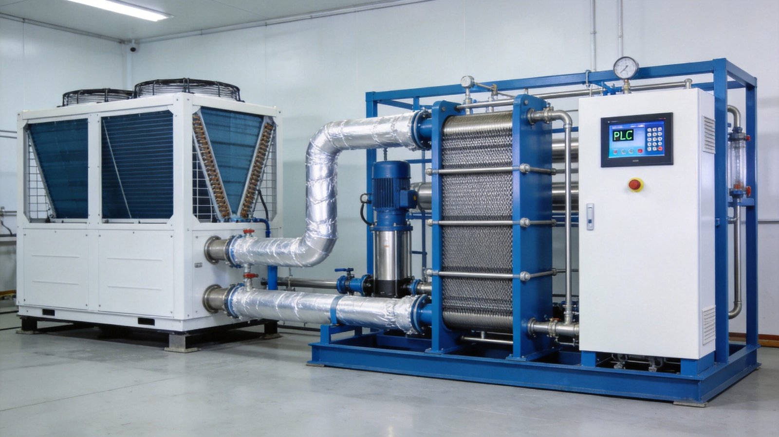
An undersized or poorly specified sodium hypochlorite generator cooling loop quietly shortens membrane life, inflates chlorate by-product, and erodes current efficiency — often for years before anyone connects the dots. In high-concentration (10–15%) membrane-cell systems, roughly one-third of the DC power fed to the electrolyzer leaves as heat, and that heat has to go somewhere. If it goes into the electrolyte, the product, and the cell hardware, you pay for it three times: in lost efficiency, in accelerated hardware degradation, and in a hotter, less stable product that decomposes faster in storage. This guide covers the engineering of cooling systems for high-concentration sodium hypochlorite generators: where the heat comes from, how to calculate the load, cooling architecture options, chiller sizing and selection, heat exchanger materials, and the temperature control strategy that ties it all together.
- Why Temperature Control Matters in High-Concentration NaClO Generation
- Where the Heat Comes From: Electrolyzer Heat Balance
- Sodium Hypochlorite Generator Cooling Architectures: Chiller, Once-Through and Hybrid
- Chiller Sizing and Selection Criteria
- Heat Exchanger Design: Materials and Thermal Sizing
- Temperature Setpoints and Control Strategy
- Common Cooling System Design Mistakes
- Frequently Asked Questions
Why Temperature Control Matters in High-Concentration NaClO Generation
Membrane-cell sodium hypochlorite generation has a narrow thermal sweet spot, roughly 30–40 °C at the cell outlet. Stray outside it and four things degrade simultaneously:
- Current efficiency. Below ~25 °C, electrolyte conductivity and membrane ion mobility drop, cell voltage climbs, and you burn more kWh per kilogram of available chlorine. Above ~40 °C, parasitic reactions — oxygen evolution at the anode and chlorate formation in the bulk — consume an increasing share of the current.
- Chlorate by-product. The disproportionation reaction 3NaOCl → NaClO₃ + 2NaCl is strongly temperature-accelerated, and it is already faster in 10–15% product than in the 0.6–0.8% solution produced by seawater electrochlorinators. Chlorate is a regulated disinfection by-product — the WHO Guidelines for Drinking-water Quality set a provisional guideline value of 0.7 mg/L — so every degree of unnecessary heat in the electrolyzer and product tank shows up later as a compliance headache at the dosing point. We cover the storage-side chemistry in our article on sodium hypochlorite stability control.
- Membrane life. Perfluorinated ion exchange membranes are robust, but their carboxylate/sulfonate polymer structure ages faster at elevated temperature, especially in contact with hypochlorite. Sustained operation above 40–45 °C measurably shortens membrane service life — see the failure mode analysis in our membrane degradation guide.
- Electrode coating wear. RuO₂/IrO₂ mixed-metal-oxide anode coatings dissolve slowly in service, and both the electrochemical and chemical attack rates rise with temperature. Cooling is therefore a direct lever on electrode recoating intervals, alongside the operating practices described in electrode material selection and lifetime optimization.
In short: cooling is not an accessory. It is a process control system that protects the two most expensive consumables in the plant — the membrane and the electrode coating — and the quality of the product itself.
Where the Heat Comes From: Electrolyzer Heat Balance
The dominant heat source is the electrolyzer itself. A membrane cell operating at 4–6 kA/m² runs at a cell voltage of 3.0–3.3 V, while the thermoneutral voltage of the overall reaction is only about 2.2 V. Everything above the thermoneutral voltage converts to heat inside the cell:
Qcell (kW) = I (kA) × (Vcell − 2.2)
Using the Faraday yield of 1.323 kg Cl₂ per kA·h, the heat load scales directly with plant capacity. The table below shows the numbers for 12% available-chlorine plants at 3.2 V cell voltage:
| Plant Capacity (12% NaClO) | Cl₂ Production (kg/h) | DC Current (kA) | Cell Heat Load (kW) | Recommended Chiller (kW)* |
|---|---|---|---|---|
| 1 t/d | 5.0 | 3.8 | 3.8 | 4.7 (≈2 HP) |
| 3 t/d | 15.0 | 11.3 | 11.3 | 14.2 (≈5 HP) |
| 5 t/d | 25.0 | 18.9 | 18.9 | 23.6 (≈8 HP) |
| 10 t/d | 50.0 | 37.8 | 37.8 | 47.2 (≈17 HP) |
*Chiller capacity includes a 1.25 design safety factor. 1 HP of refrigeration ≈ 2.8 kW cooling.
Worked example — 10 t/d plant: 10,000 kg/d × 12% = 1,200 kg/d of available chlorine, i.e. 50 kg/h of Cl₂ equivalent. That requires 50 ÷ 1.323 ≈ 37.8 kA of DC current. At 3.2 V, the electrolyzer dissipates 37.8 × (3.2 − 2.2) ≈ 37.8 kW of heat. Add a 25% margin and the chiller selection lands at ≈47 kW, or about 17 HP of refrigeration. With a 5 °C temperature rise across the cooling loop, the required coolant flow is roughly 6.5 m³/h.
Two secondary heat sources deserve a line in the budget. The rectifier converts 3–6% of its throughput to heat (about 4–7 kW for a 121 kW DC supply), which is normally rejected to the room air rather than the process loop — but it must be included in the room ventilation calculation. And if you cool the product stream before storage (recommended, see below), the product sensible heat adds to the chiller duty. The electrical side of this balance connects directly to the rectifier sizing logic in DC power supply and rectifier design.
Sodium Hypochlorite Generator Cooling Architectures: Chiller, Once-Through and Hybrid
Three architectures cover virtually all high-concentration installations:
- Closed-loop chiller + titanium plate heat exchanger. The standard for brine-based 10–15% systems. A packaged air- or water-cooled chiller circulates coolant (water or water-glycol) through a titanium plate exchanger that cools the recirculating electrolyte. The process side stays fully closed: no scaling, no contamination, precise temperature control, and independence from raw water quality and availability. This is the default architecture in QINGY 1–15 t/d systems.
- Once-through raw water or seawater. Feasible where a reliable supply of cool water (≤25 °C year-round) exists — coastal power plants, desalination pretreatment, river intakes. Capital cost is low, but you inherit fouling, biological growth, and seasonal temperature swings, and the exchanger must be titanium on the raw-water side as well. Discharge thermal limits and water rights can also constrain this option.
- Cooling tower + plate heat exchanger (hybrid). For larger plants (≥10 t/d) in water-scarce regions, an evaporative tower rejects the bulk of the heat at far lower electrical cost than a chiller, with a small trim chiller or bypass control holding the final setpoint. The tower loop stays on the clean side of the plate exchanger; the electrolyte never sees the open circuit.
For most municipal and industrial users in the 1–8 t/d range, the packaged chiller loop wins on simplicity, footprint, and control precision. Above ~10 t/d, run the lifecycle cost comparison: a chiller’s electrical draw adds roughly 8–15% on top of the electrolyzer’s own consumption, which is worth scrutinizing in any system cost analysis.
Chiller Sizing and Selection Criteria
Once the heat load is known, specifying the sodium hypochlorite generator cooling package comes down to five engineering decisions:
- Capacity with margin. Multiply the cell heat load by 1.2–1.3. This covers fouling allowance, refrigerant aging, the hottest design day, and the product-cooling duty if it shares the loop. Never size a chiller flat to the calculated load — refrigeration capacity also falls as ambient temperature rises.
- Ambient rating. Air-cooled chiller capacities are quoted at 35 °C ambient. For Middle East, North Africa, or enclosed-container installations at 45–50 °C ambient, expect a capacity derate of roughly 1–1.5% per °C above rating — a 47 kW requirement can demand a unit nominally rated 55 kW or more. This is the single most common sizing error we see in export projects, and it applies equally to containerized systems where condenser air recirculation can make the effective ambient even hotter.
- Wetted materials. On the coolant (clean) side, 304 stainless steel plate and piping is acceptable. Any component that can contact electrolyte or product — the process-side exchanger plates, pumps, strainers — must be titanium or suitable fluoropolymer. Copper-brazed heat exchangers and copper-nickel alloys are forbidden anywhere near chlorinated brine or hypochlorite.
- Temperature control accuracy. Specify digital PID control to ±1 °C with a supply-temperature sensor, plus a Modbus/RS485 or 4–20 mA interface so the generator PLC can read coolant temperature and chiller status, and can trip the rectifier on cooling failure.
- Reliability. On plants that run 24/7, the coolant circulation pump should be duplex (duty/standby with auto-changeover), and the chiller itself should have a low-flow bypass and freeze protection if installed outdoors in cold climates (30–40% propylene glycol where frost is possible).
Heat Exchanger Design: Materials and Thermal Sizing
The plate heat exchanger is where material mistakes become expensive. The electrolyte stream is hot, chlorinated, and oxidizing; the hypochlorite product stream is even more aggressive. The proven specification:
- Plates: commercially pure titanium (Grade 1 or 2). Titanium forms a self-healing oxide film that is effectively immune to chlorinated brine and sodium hypochlorite at generator temperatures. 316L stainless is not adequate for the electrolyte side; copper alloys fail rapidly.
- Gaskets: EPDM. Butyl rubber tends to crack in strong oxidizing service, nitrile is unsuitable, and fluorocarbon (FKM) is reserved for the most aggressive spots. Clip-on gaskets simplify the frequent inspection that oxidizing service demands.
- Thermal sizing: design for a close approach of 3–5 °C between coolant supply and electrolyte return, and include a fouling margin of 10–20% on the heat transfer area. Brine-side velocities should stay in the turbulent range to limit scale deposition from any residual hardness — the same hardness control logic covered in our brine purification system design guide protects the exchanger as much as the membrane.
- Serviceability: specify a frame with at least 20% spare plate capacity, full drain and vent connections, and isolation valves so the pack can be opened, inspected, and cleaned without draining the whole loop.
Where the product stream is cooled before the storage tank, use a second small titanium plate exchanger (or a titanium coil in the day tank). Dropping 10–15% product from a 35–40 °C cell outlet to ≤25 °C before storage roughly halves the decomposition and chlorate-formation rates — the single cheapest product-stability measure available, and a natural extension of the practices in why high-concentration sodium hypochlorite decomposes faster.
Temperature Setpoints and Control Strategy
A defensible control philosophy for a high-concentration membrane-cell plant looks like this:
- Electrolyte supply to cell: 25–30 °C, held ±1 °C by the chiller loop.
- Cell outlet: ≤40 °C, giving a ΔT of 5–10 °C across the cell at rated current. Rising ΔT at constant current is an early diagnostic of flow restriction or scaling.
- Product to storage: ≤25 °C (20–25 °C ideal) after the product cooler.
- Alarms and trips: high cell-outlet temperature alarm at 42 °C; rectifier trip at 45 °C; coolant low-flow alarm and rectifier interlock; chiller fault signal wired into the generator PLC so the plant cannot run “blind” without cooling. These interlocks belong in the cause-and-effect matrix from day one, alongside the hydrogen and level protections described in our hydrogen safety engineering guide.
Trend cell inlet/outlet temperature, coolant supply temperature, and chiller suction/discharge pressures in the SCADA historian. A slow upward drift in coolant supply temperature is usually condenser fouling (air-cooled) or refrigerant loss — both cheap to fix if caught early, both destructive if the cell runs hot for a summer. Remote trending of exactly these points is a natural fit for the SCADA and IoT monitoring architecture we have described previously.
Common Cooling System Design Mistakes
Most sodium hypochlorite generator cooling failures we audit trace back to six recurring specification errors:
- Sizing the chiller to the nominal load with no ambient derate — the plant passes FAT in spring and trips on high cell temperature every August.
- Copper-brazed or stainless exchangers on the brine side — pitting and crevice corrosion breach the plates, coolant contaminates the electrolyte, and the membrane is poisoned by hardness ions before the leak is even found.
- Single coolant pump — a $400 pump becomes the single point of failure that trips a $200,000 generator. Duplex with auto-changeover.
- Measuring temperature at the cell inlet only — the membrane lives at the outlet conditions. Instrument both; alarm on outlet.
- Sending hot product straight to the tank — every degree above 25 °C accelerates chlorate growth and available-chlorine decay through the whole storage period.
- Ignoring the maintenance loop — condenser coil cleaning, glycol concentration checks, and plate-pack inspection must be on the preventive schedule, as laid out in our electrochlorination maintenance guide.
Frequently Asked Questions
What temperature should a high-concentration sodium hypochlorite electrolyzer run at?
Aim for 25–30 °C electrolyte at the cell inlet and no more than 40 °C at the outlet — a 5–10 °C rise across the cell at rated current. This band balances electrolyte conductivity and membrane performance against chlorate formation and coating wear. Alarm at 42 °C and trip the rectifier at 45 °C.
Can I cool the electrolyzer with raw water instead of a chiller?
Yes, if you have a dependable supply at ≤25 °C all year and adequate flow (about 6.5 m³/h per 10 t/d of capacity at a 5 °C rise). Use a titanium plate exchanger between the raw water and the electrolyte, and plan for fouling control and seasonal temperature swings. For most brine-based plants without a suitable water source, a packaged chiller is simpler and gives far tighter temperature control.
What happens if cooling fails while the generator is running?
Cell temperature climbs within minutes. Current efficiency falls, chlorate formation accelerates, and sustained operation above 45 °C damages the membrane and anode coating. This is why coolant low-flow and high cell-outlet temperature must be hardwired to trip the rectifier — the plant should never run without confirmed cooling.
Air-cooled or water-cooled chiller?
Air-cooled is the default for 1–8 t/d plants: no cooling tower, no water treatment, minimal installation work. Water-cooled units are more efficient and quieter but need a tower or plant cooling-water supply, so they mainly make sense above ~10 t/d or where the site already operates a cooling tower. In hot climates, remember to derate air-cooled capacity by roughly 1–1.5% per °C above the 35 °C rating point.
Do I really need to cool the product before the storage tank?
For 10–15% product, strongly recommended. Product leaving the cell at 35–40 °C decomposes and forms chlorate at roughly twice the rate of product stored at 20–25 °C. A small titanium plate exchanger on the product line is one of the lowest-cost stability upgrades in the entire plant.
Conclusion
The cooling system of a high-concentration sodium hypochlorite generator is a process system, not a utility afterthought. Calculate the cell heat load from current and cell voltage (Q = I × (Vcell − 2.2)), add a 1.2–1.3 design margin, derate for the real summer ambient, and specify titanium wetted parts with EPDM gaskets throughout the process side. Hold 25–30 °C at the cell inlet, alarm at 42 °C and trip at 45 °C at the outlet, and cool the product to ≤25 °C before storage. Get the sodium hypochlorite generator cooling design right and the membrane, electrodes, and product quality will all return the favor over years of service.
QINGY supplies complete 1–15 t/d high-concentration sodium hypochlorite generation systems with engineered cooling packages — chillers, titanium plate heat exchangers, duplex coolant pumps and PLC temperature interlocks — designed as one integrated skid. To review cooling requirements for your site conditions, contact our engineering team or explore the high-concentration generator product line.